This case study presents a few of our more interesting FEA consulting service projects that we have done on transmission, gearbox and drive train components over the last several years. Most of the work involves nonlinear contact, bolt preload and detailed stress and vibration analysis toward durability analysis of the components.
FEA simulattions discussed are:
- Heavy-Duty Electric Utility Vehicle Gearbox and Differential Housing
- Dual-Cylinder Motorcycle Engine Gearbox and Housing
- Transmission analysis of dual-shaft 3,000 HP gearbox
- Transmission Shifting Mechanisms
- Hydraulic Variable Speed Transmission Housing Analyses
- Large-Scale Gearbox for Off-Shore Drilling Platform Winch
Video Summary of our FEA Consulting Projects on Transmissions, Gearboxs, Hydraulic Variable Speed Housings and Drive Train Components
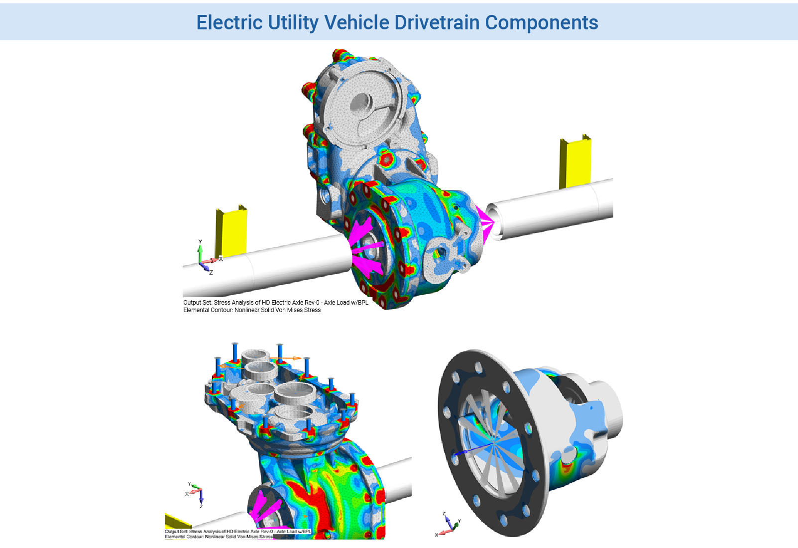 Figure 1: Stress and fatigue analysis gearbox and drivetrain components for a light-weight electric utility vehicle. The FEMAP model was analyzed using NX Nastran SOL 601 (ADINA).
This was a classic stress analysis of a gearbox housing. It is something we done many times at Predictive Engineering for off-shore equipment, motorcycles, automotive, aerospace and now for a small electric utility vehicle. The client was great to work with and supplied us with the load path breakdown from gear-to-gear-to-gear. Although this is something we have done in the past, teamwork is always great since it helps prevents cross-communication. The objectives of this work was to determine stress levels in the gearbox housing to assess durability and if, there would be sealing issues between the main casing and its cover. Oil leakage between seals can be determined via contact pressure plots. The trick on such work is to ensure sufficient mesh density between the contacting surfaces that one sees true pressure and not a mesh artifact. Prior work with Norton Motorcycles helped to refine this seal analysis. Final results showed that the design was adequate for service and would be “leak free”.
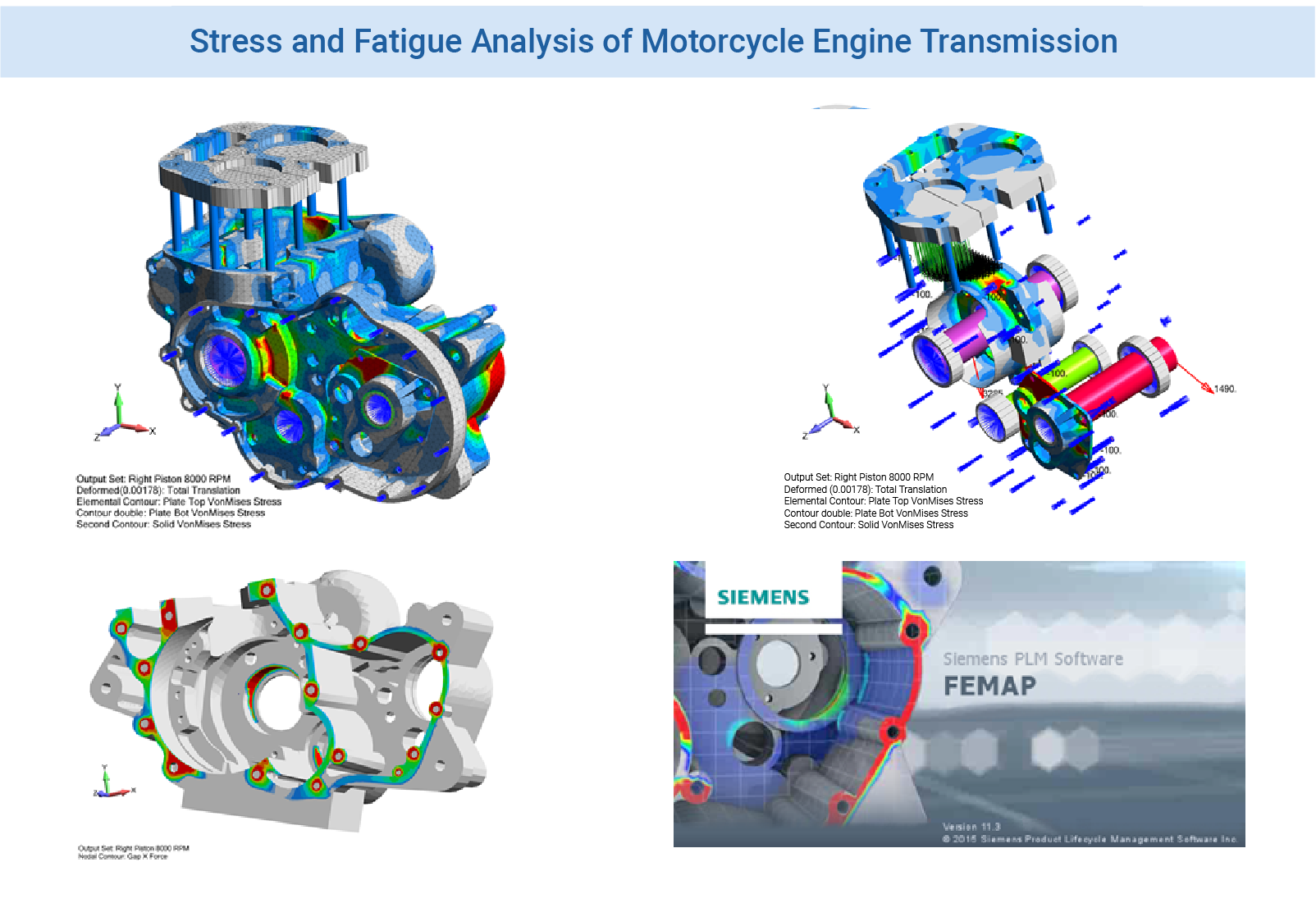
Figure 2: Stress and fatigue study of an cast aluminum motorcycle engine. A maximum load analysis was performed at 8,000 RPM along with an oil seal analysis on the crankcase. This work has been featured by Siemens in several publications.
This work was done to support the re-birth of the Norton Motorcycle. In cooperation with their engine expert, we developed the load profile for maximum crankcase load. For motorcycle enthusiasts it will be no surprise that the maximum crankcase bearing load occurs when the throttle is released at maximum RPM. Without the corresponding combustion force, the inertia forces of the piston will tear the engine apart if not carefully designed to handle this load. Contact was used between all bearing surfaces to allow the quick analysis of various load cases. Of key importance to the client was to ensure that the crankcase would not leak oil. A sealing analysis of the crankcase was then done to determine the contact pressures along the main seal under bolt preload and under all load cases. This work was published by Siemens in several news announcements and is used in several publications in relation to their FEA software (FEMAP and NX Nastran).
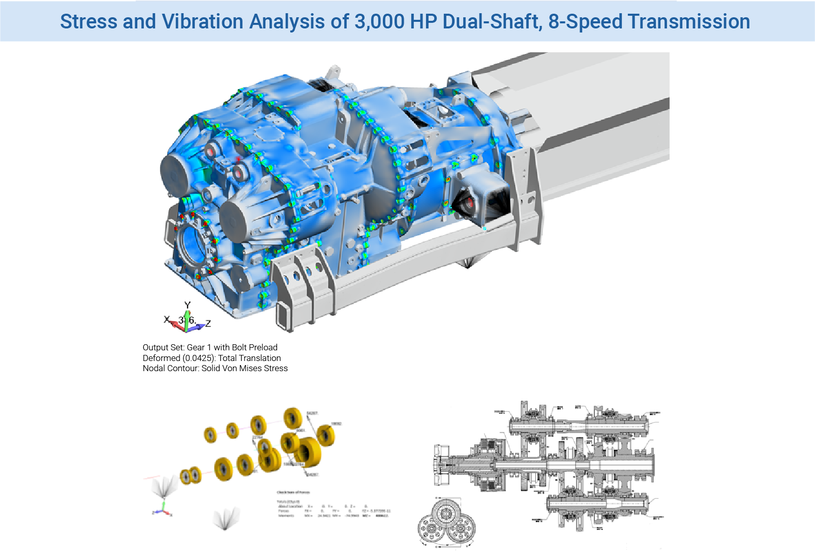
Figure 3: Stress and vibration analysis of 3,000 HP, Dual-Shaft, 8-speed transmission for the efficient pumping of heavy fluids
This FEA consulting project started from initial concept and was carried forward to a field tested 3,000 HP transmission. It was the first of its kind using a compact dual-shaft arrangement to provide 8-speeds off of a 12 cylinder diesel engine running at 2,300 RPM. The bearing forces were calculated based on gearing arrangement (1st gear to 8th gear) and input torque. Contact was used to simulating the shaft loading into bearings and then into the cast ductile iron transmission housing. The sectional housing (four main sections) was bolted together with contact enforced across the bolt preloaded interface. The dominate load case for the transmission housing was, of course, 1st gear. The analysis work studied bolt loading for long-term life based on the end-clients own internal transmission bolt specifications along with stress limits based on the long-term fatigue life of their transmission and bolt materials. The model shown in the graphic had 3+ million nodes and captured nonlinear bolt pre-load with contact. Additionally, a normal modes (eigenvalue) analysis was performed to determine the first significant vibration modes. The objective was to ensure that the first mode of the transmission assembly was higher than the diesel engine. The model was validated during operational tests from stress to vibration to “oil-tight sealing” at all assembly joints.
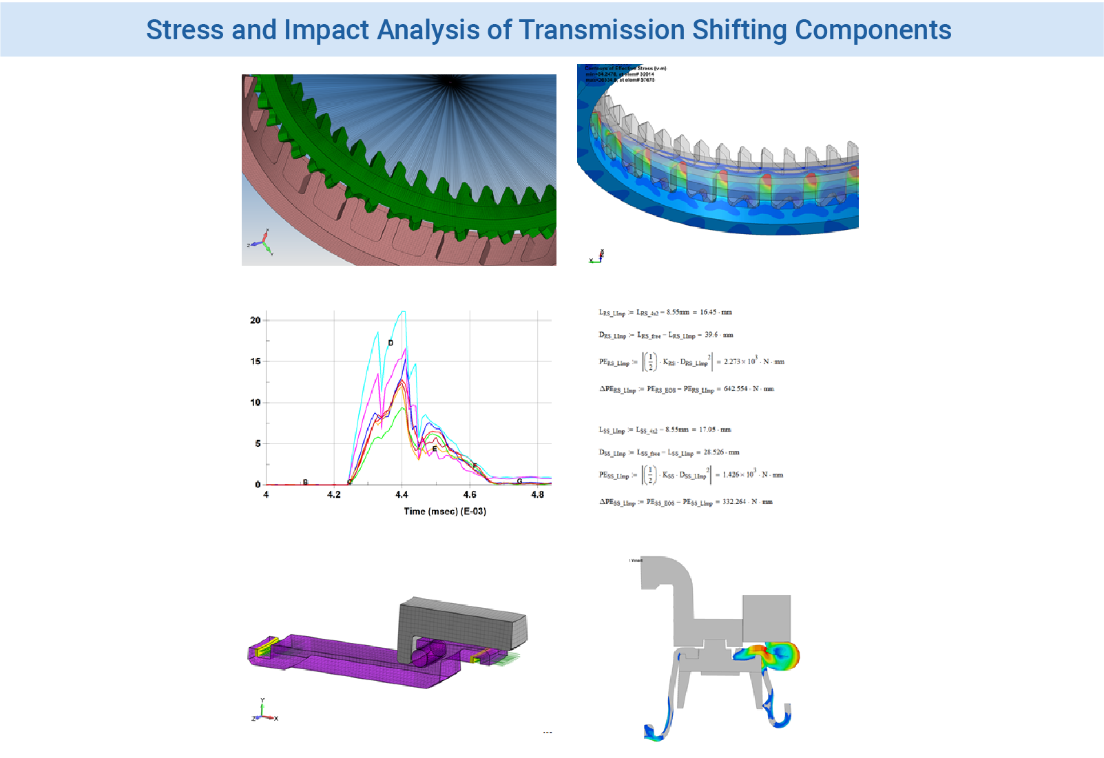
Figure 4: FEA simulation of transmission shifting components from teeth to O-rings provided detailed design verification and assurances against in-the-field fatigue failures
Working with well-known automotive supplier of transmission shifting mechanisms, we assisted their team in the verification of a new compact device for 4×4 vehicles. One of their concerns was the dynamic nature of the shifting event under various speeds. The model was run using LS-DYNA allowing us to capture the complete transient, nonlinear response of the tooth sets interacting at design speeds. The work was verified internally by Predictive Engineering by hand calculations to ensure that the loading and the output results were reflecting reality. Our experience has taught us to never fully trust FEA results until they have been verified by as many alternative methods as may be possible.
The shifting mechanism used a large diaphragm rubber seal to maintain oil integrity. This seal had several operating regimes from normal to extreme crushing due to improper use. To ensure the robustness of the device we looked at several seal configurations. The model was run as quasi 3D (periodic symmetry) and also as axisymmetric. The shifter is in use today and has meet our clients requirements for smooth operation and durability.
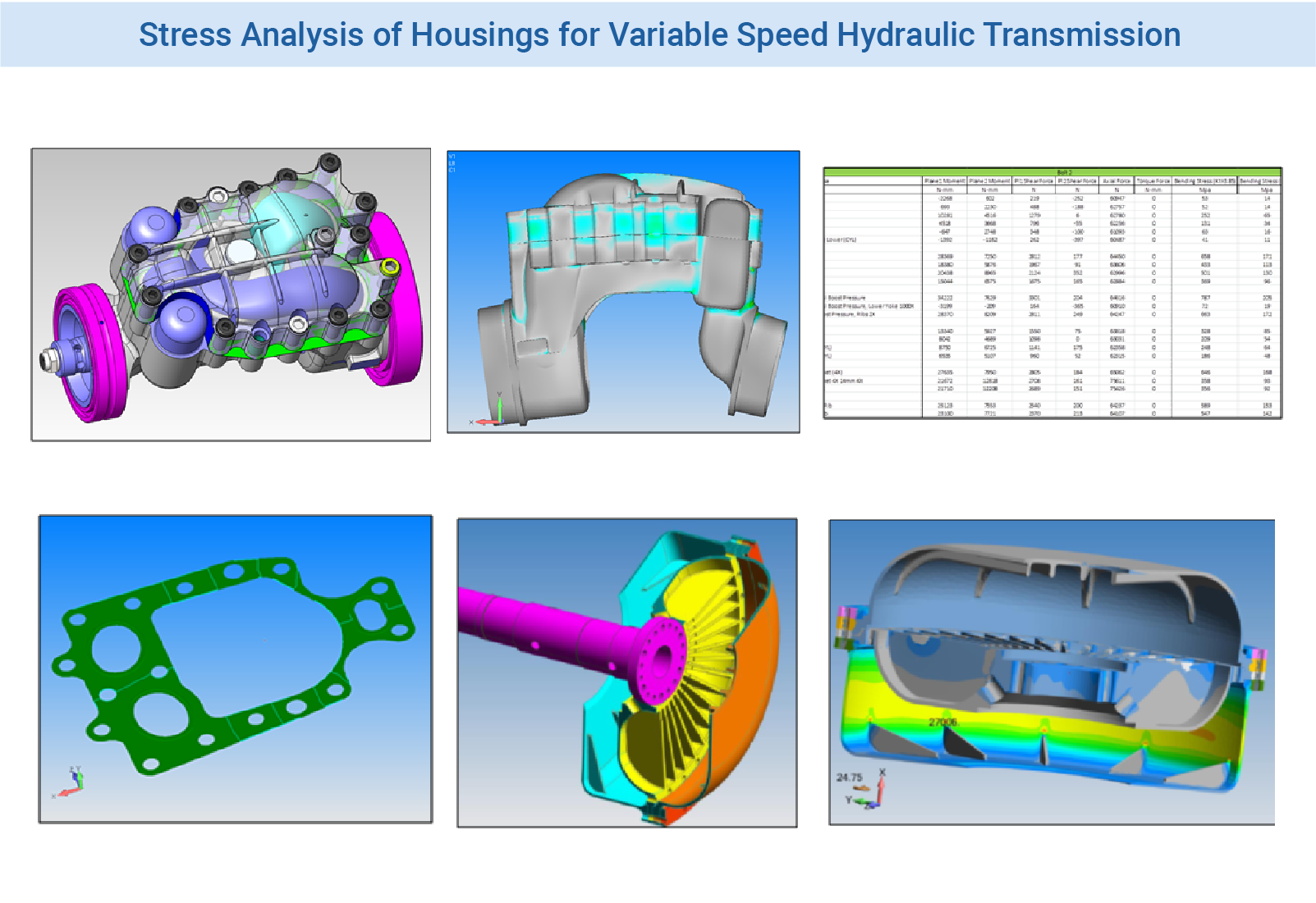
Figure 5: Two examples of hydraulic variable speed transmissions were studied. Stresses in the transmission cases were driven by hydraulic pressures and fluid operating temperatures (thermal-stress). Bolt load failure analysis was pivotal in both transmissions to ensure their in-the-field durability
Hydraulic variable-speed transmissions have been used for decades. In these two FEA consulting projects for different clients, we investigated the stress and thermal-stress response of the transmission housings. In the first project, the client was interested in improving the seal performance of the top head gasket. Besides the usual stress analysis under operating pressure we did a complete bolt analysis (spreadsheet based from FEA bolt axial and shear loads) to a gasket analysis. Our recommendation was quite simple – use a higher bolt preload. In the second FEA project, the client was having problems with the system once it had been in operation for a few hours. Due to thermal growth of the components (aluminum impeller matched up with a ductile iron housing), some binding was occurring between the components causing bolt breakage. The FEA model was able to accurate predict this behavior and the manufacturing tolerances were modified to allow for additional clearance along with thinning out a few regions to allow for greater flexibility during thermal expansion.
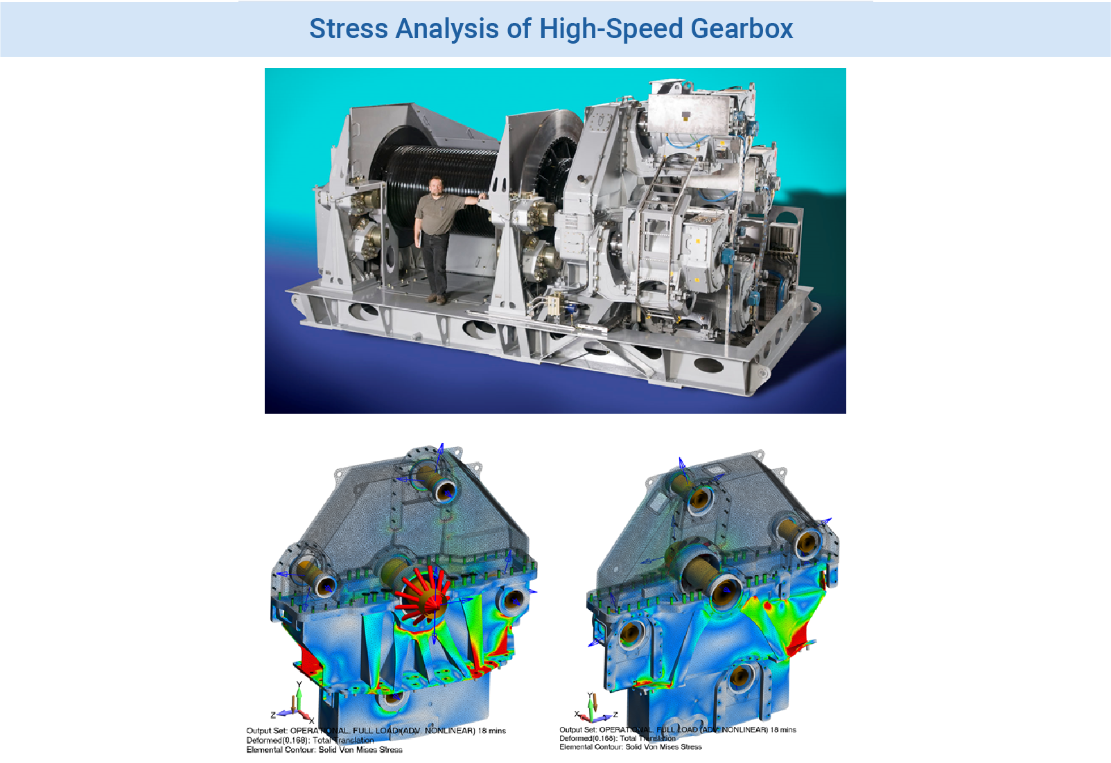
Figure 6: Gearbox analysis for high-speed, off-shore winch. The gearbox is driven by three electric motors mounted on the back side of the gearbox
The complete structure from gearbox, electric motor support frame, winch calipers, winch drum and frame assembly was analyzed by Predictive Engineering. The analysis consisted of a global loads model for the frame and then several detailed sub models for the winch drum, bearings, brakes and support frames. The gearbox was to itself a major analysis. The gear loads were calculated based on motor torques (three) and gear ratios. These loads where then transferred via frictionless bearings (contact analysis) into the gearbox. The gearbox parting line was bolt preloaded with contact to determine its oil seal tightness and fitness for service. Major hotspots in the gearbox were redesigned and when possible low stress regions decreased in thickness. Weight optimization was a key objective since this structure is required to be flown to site, assembled and then operated on a ship based platform. The stress analysis was validated by the long-term operation of the winch system.


