
Expand your abilities with NX CAD resources
NX CAD resources
Filter:
All
By type
By category
-
 Tutorials
Model-based definition and the application of technical data packages
July 17, 2024Read more -
 Tutorials
NX Wave Linking best practices 2024
July 10, 2024Read more -
 Seminar
NX Large Assembly Best Practices
February 02, 2024Read more -
 Seminar
NX Managed: Wave Linking the Applied Way
February 01, 2024Read more -
 Seminar
Automating NX CAD without custom scripts
November 16, 2023Read more -
 Seminar
Introduction to Simulation-Driven Design in NX
November 19, 2021Read more -
 Seminar
New Developments in PMI and Model-Based Definition
November 19, 2021Read more -
 News
NewsHow to Update to the latest NX Release | Siemens NX Continuous Release
March 23, 2021Read more -
 Tutorials
NX CAD: 10 Best Practices for Improving Workflow
February 26, 2021Read more -
 News
NewsNX 1926: What’s new in Sketch
November 19, 2020Read more -
 Seminar
NX and Working with PMI-MBE Technical Data Packages
October 21, 2019Read more -
 Seminar
How to Use the NX Open Reporter Tool – Video Tutorial
August 01, 2019Read more -
News
What’s New with PMI in NX 1847 Continuous Release
February 06, 2019Read more -
News
What is NX Continuous Release, and will NX 13 ever come out?
January 29, 2019Read more -
 Tutorials
Synchronous Modeling video tutorial 04: Move Face and Blends
December 18, 2018Read more -
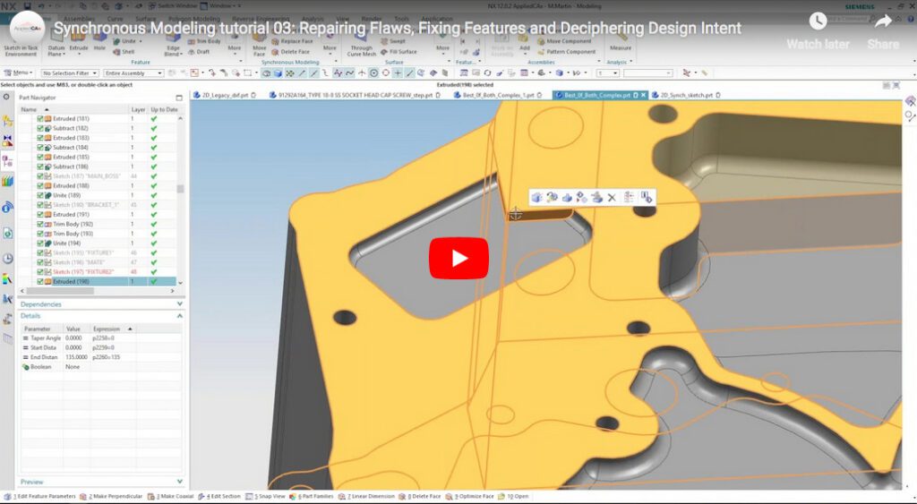 Tutorials
Synchronous Modeling video tutorial 03: Repairing Flaws, Fixing Features and Deciphering Design Intent
December 18, 2018Read more -
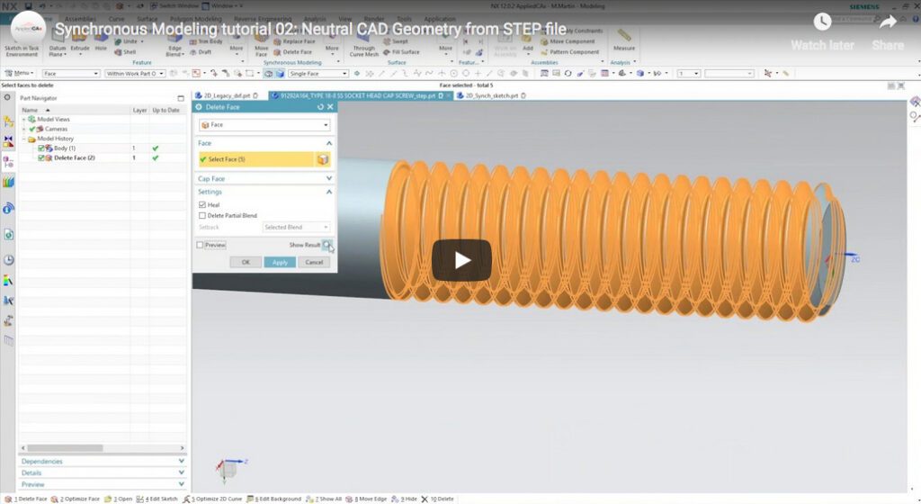 Tutorials
Synchronous Modeling video tutorial 02: Neutral CAD Geometry from STEP file
December 18, 2018Read more -
 Tutorials
Synchronous Modeling video tutorial 01: 2D Synchronous Modeling
December 18, 2018Read more -
Seminar
NX Programming and Customization with NX Open
October 30, 2018Read more -
News
What’s New in NX 12 and the Future of NX – Seattle NX User’s Group Oct 2018
October 30, 2018Read more -
Seminar
Synchronous Modeling Workflows and Why You Want to Use Them
October 05, 2018Read more -
News
Sketch Reattach in NX CAD
September 19, 2018Read more -
 Seminar
NX Open – Customization & Automation Services
July 30, 2018Read more -
Tutorials
How to Create Designs Using Topology Optimization in NX
July 23, 2018Read more -
Tutorials
New Motorcycle Blinkers Part 2: Using Clean-up Tools for your Topology Optimization Results
July 18, 2018Read more -
 News
NewsWhat’s New in NX 12.0.2
July 17, 2018Read more -
Tutorials
Convergent Modeling tools to improve your Topology Optimization results – NX CAD Tips & Tricks Video
July 16, 2018Read more -
Tutorials
NX Open Tutorial – Improve Your Workflows
June 21, 2018Read more -
 Tutorials
From CAD to Creation – Making a new motorcycle blinker using Topology Optimization
June 19, 2018Read more -
 News
NewsBig changes ahead as NX shifts to Continuous Release versions
June 05, 2018Read more -
News
What’s new in NX 12 – CAD Modeling
April 23, 2018Read more -
Tutorials
Methods for Moving Your CAD Data to NX
April 10, 2018Read more -
News
What’s New in NX 12 – Changes in the User Interface Part 2
February 23, 2018Read more -
 Tutorials
How to Install NX 12.0.1
February 19, 2018Read more -
News
What’s New in NX 12 – Changes in the User Interface Part 1
February 09, 2018Read more -
Tutorials
How to Generate a New License File for NX 12
November 16, 2017Read more -
Tutorials
How to Update Legacy NX Drawings for PMI – NX CAD tips and tricks
September 19, 2017Read more -
 Seminar
Visualization Templates – NX CAD Tips and Tricks
September 07, 2017Read more -
 Tutorials
Examine Geometry & Heal Geometry – NX CAD Tips and Tricks
July 14, 2017Read more -
News
What’s New in NX CAD 11 – Tips and Tricks Webinar Tutorial
July 12, 2017Read more -
Tutorials
The Siemens Machinery Library – NX Engineering Tips and Tricks
May 05, 2017Read more -
Seminar
Overview of Convergent Modeling, 3D Printing and Additive Manufacturing with NX
February 28, 2017Read more -
Tutorials
Mechanical Routing, Flexible Hose – NX CAD tips and tricks tutorial video
June 16, 2016Read more -
 Tutorials
Video Tutorial – NX PMI/MBD for Designers and Engineers
April 12, 2016Read more -
 Tutorials
NX CAD Ten Best Practices, Tips and Tricks
March 18, 2016Read more -
Tutorials
NX Law Extension tips and tricks tutorial video
March 13, 2016Read more -
Tutorials
NX CAD Blend Corner tips and trick video tutorial
March 11, 2016Read more -
Tutorials
NX Fill Surface tips and tricks video tutorial
March 06, 2016Read more -
Tutorials
Siemens NX9 Installation
November 20, 2013Read more -
Tutorials
Siemens NX – How to Setup a New Webkey Account
November 20, 2013Read more -
Tutorials
Siemens NX Log File
March 28, 2013Read more
Resources—applied
Explore our resources hub for additional Siemens software resources.
It’s time to unleash your potential
Reach out to the team at Applied CAx to learn how our solutions can make your company’s goals achievable.